
An isomerization unit is a refinery process unit that rearranges the molecular structure of light straight-run naphtha — specifically C5 and C6 hydrocarbons — into higher-octane branched isomers, without changing the chemical formula. In practical terms, it is one of the most cost-effective ways a refinery can boost the octane rating of gasoline blending components and meet tightening fuel quality regulations. If you work in refining or are studying process engineering, understanding the isomerization process is fundamental to understanding modern gasoline production.
“Many refinery operators consider the isomerization unit one of the quietest units in the gasoline section — until feed contamination or chloride corrosion suddenly creates major operational headaches.”
an isomerization unit converts low-octane linear hydrocarbons (C5/C6 paraffins) into high-octane branched isomers using heat, pressure, and a catalyst — typically platinum on a chlorinated alumina or zeolite base — without altering the molecular formula, only the molecular arrangement.
What Is Isomerization? A Simple Answer Before We Go Deeper
Isomerization is a chemical reaction in which a molecule is rearranged into a different structural form — called an isomer — while keeping the same number and type of atoms. In refinery applications, the isomerization process targets n-pentane (n-C5) and n-hexane (n-C6), both of which have a low Research Octane Number (RON). The unit converts these straight-chain molecules into their branched counterparts — isopentane and isohexane — which have significantly higher RON values.
What is called isomerization in chemistry is simply the process of creating an isomer. In a refinery context, the term is applied specifically to the catalytic rearrangement of paraffins to improve fuel quality. The reaction is reversible and thermodynamically limited, which is why most modern isomerization units include a deisopentaniser column or a recycle loop to push conversion higher.
Key point: Isomerization does not crack or reform molecules — it only rearranges them. This makes it a gentler, lower-severity process compared to catalytic reforming, and it produces no significant coke or heavy by-products under normal operation.
Why Does the Isomerization Process Matter in a Refinery?
The use of isomerization in modern refining has grown considerably since regulations began restricting benzene content in gasoline and reducing the allowable aromatics pool. Catalytic reformers naturally produce high levels of benzene, so refineries need an alternative octane source for the light naphtha fraction — and the isomerization unit fills exactly that role.
What is the use of isomerization in oil processing? In short, it converts a low-value, low-octane stream into a high-value gasoline blending component. A typical straight-run naphtha C5/C6 feed has a RON of approximately 68–72. After isomerization, the product can reach RON values of 83–92 depending on the configuration and whether a recycle scheme is used.
In practice, refineries that have invested in isomerization units have significantly more flexibility in meeting Euro V and Euro VI gasoline specifications without relying entirely on reformate or alkylate. This makes the unit economically strategic, not just technically useful.
| Component | RON (Straight Chain) | RON (Branched Isomer) | Octane Gain |
|---|---|---|---|
| n-Pentane (nC5) | 61.7 | 92.3 (isopentane) | +30.6 |
| n-Hexane (nC6) | 24.8 | 74.5 (2-methylpentane) | +49.7 |
| n-Hexane (nC6) | 24.8 | 107.4 (2,2-dimethylbutane) | +82.6 |
| Cyclohexane (C6) | 83.0 | Benzene precursor — removed | Neutral |
How Does an Isomerization Unit Work? — Step by Step
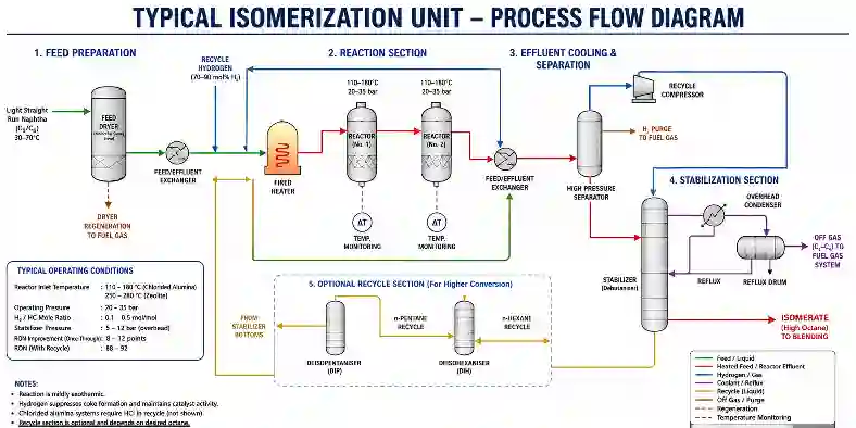
Understanding what is an isomerization unit in oil processing requires following the feed through the unit from inlet to product rundown. The process involves feed preparation, reaction, stabilisation, and in many configurations, product recycle.
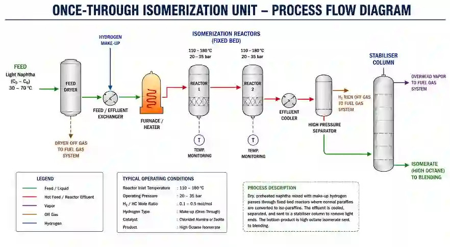
- Feed Preparation and Drying: The light straight-run (LSR) naphtha feed, typically a C5/C6 cut boiling between 30°C and 70°C (86°F–158°F), is first treated to remove water, sulphur compounds, and oxygenates. Water is particularly harmful to chlorided alumina catalysts and must be reduced to below 0.5 ppm. Feed is passed through a molecular sieve dryer before entering the reaction section. In practice, operators monitor the dryer outlet water content using an on-line moisture analyser, and dryer changeover is typically scheduled every 48–72 hours depending on feed quality.
- Hydrogen Recycle and Mix: Hydrogen is added to the feed to suppress coke formation on the catalyst and to maintain catalyst activity. Typical hydrogen-to-hydrocarbon (H2/HC) molar ratios are 0.1–0.5 mol/mol depending on catalyst type. The mixed feed is then preheated in a feed/effluent heat exchanger to recover process heat and reduce fired heater duty.
- Fired Heater: The combined feed is raised to reactor inlet temperature in a direct-fired heater. For chlorided alumina catalyst systems (e.g., UOP Penex), reactor inlet temperatures are typically 110–180°C (230–356°F). For zeolite-based catalyst systems (e.g., UOP Par-Isom), temperatures are higher — approximately 250–280°C (482–536°F). Both systems operate at pressures of approximately 20–35 bar (290–510 psi).
- Catalytic Reaction in Fixed-Bed Reactors: The preheated feed passes through one or two fixed-bed reactors containing the isomerization catalyst. The isomerization reaction is mildly exothermic. Typical reactor temperature rise (delta T) is 10–25°C across each bed. The catalyst rearranges n-paraffins to their branched isomers. Cyclohexane is converted to methylcyclopentane, and benzene is saturated to cyclohexane before further ring-opening — eliminating benzene from the product, which is a key regulatory benefit.
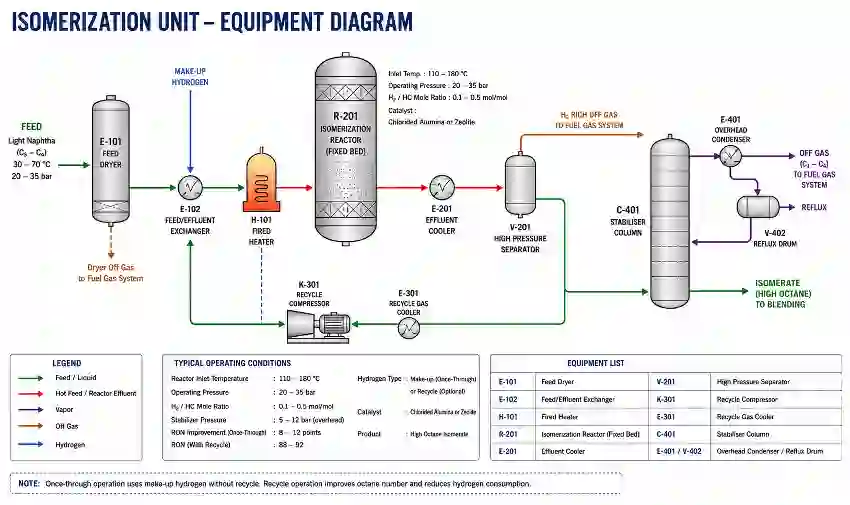
- Feed/Effluent Heat Exchange and Cooling: Reactor effluent passes through the feed/effluent exchanger, preheating the incoming feed. The cooled effluent then enters a high-pressure separator where hydrogen-rich gas is separated and recycled to the reactor inlet via a recycle compressor.
- Stabiliser Column: The liquid product from the separator is fed to a stabiliser (de-butaniser) column that removes dissolved hydrogen, C1–C4 light gases, and HCl (in chlorided alumina systems) overhead. The bottoms product is the isomerate — the final high-octane gasoline blending component.
- Optional Recycle for Higher Conversion: Once-through units achieve RON upgrades of approximately 8–10 points. To increase conversion, a deisopentaniser (DIP) column can be added to separate unconverted n-pentane for recycle back to the reactor. Full recycle configurations using a deisohexaniser (DIH) column can achieve RON values of 88–92.
Key Equipment Inside an Isomerization Unit
Feed Dryers (Molecular Sieve Vessels)
Typically two vessels operating in lead/lag mode, filled with 3A or 4A molecular sieves. Operating conditions: ambient to 70°C on adsorption, 200–300°C on regeneration. Inspection focuses on vessel internals, nozzle condition, and distributor integrity. What inspectors commonly find is channelling of the molecular sieve bed after multiple regeneration cycles, which reduces effective drying capacity and results in premature catalyst deactivation downstream. API 510 governs pressure vessel inspection for these vessels.
Fixed-Bed Reactors
The reactors are the heart of the isomerization process. Typically vertical, downflow vessels fabricated in carbon steel or 1.25Cr–0.5Mo alloy. Operating pressure: 20–35 bar (290–510 psi). Operating temperature: 110–280°C depending on catalyst type. Internal components include inlet diffuser, catalyst support grids, thermocouple trees, and quench nozzles. Corrosion risks include hydrogen embrittlement at the welds and HCl corrosion in chlorided systems. ASME Section VIII and API 510 govern inspection intervals.
Recycle Compressor
A centrifugal or reciprocating compressor that circulates hydrogen-rich gas from the separator back to the reactor inlet. Typical suction pressure: 20–30 bar. Critical inspection item: seal system condition, valve condition on reciprocating machines, and impeller corrosion from HCl carry-over. API 618 (reciprocating) and API 617 (centrifugal) are the governing standards.
Stabiliser Column
A distillation column, typically 1–1.5 m diameter, operating at approximately 5–12 bar overhead pressure with a bottoms temperature of 120–160°C. Tray condition and overhead condenser inspection are key maintenance items. In chlorided systems, the overhead accumulator and reflux drum must be inspected for HCl-induced corrosion — both on internal surfaces and at overhead vapour nozzle connections. API 571 (Hydrochloric Acid Corrosion) directly applies.
Deisopentaniser / Deisohexaniser Columns (Recycle Configurations)
Larger fractionation columns used to separate unconverted n-paraffins for recycle. These operate at lower pressures (near atmospheric to 5 bar) and are less aggressive from a corrosion standpoint. In practice, tray fouling from polymer formation on the feed trays is the most common maintenance issue found during turnarounds, particularly when feed quality upsets have introduced oxygenates or diolefins.
What Products or Outputs Does an Isomerization Unit Produce?
Isomerate (Main Product)
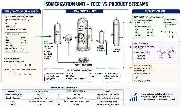
The primary output of an isomerization unit is the isomerate — a high-octane, low-benzene C5/C6 blending component for the gasoline pool. Typical specifications: RON 83–92 (configuration dependent), benzene content below 0.1 vol%, sulphur below 10 ppm. The isomerate is typically blended directly into the final gasoline blend or into the reformate blending pool. Its low aromatics and zero benzene content make it particularly valuable for meeting Euro VI and EPA Tier 3 fuel standards.
LPG / Light Ends (By-product)
The stabiliser column overhead produces a small stream of C3/C4 LPG and non-condensable hydrogen-rich off-gas. This stream is typically routed to the refinery fuel gas system or recovered in the LPG treating unit. Volume is modest — approximately 0.5–2 wt% of fresh feed — but it must be accounted for in the material balance and yield analysis.
Hydrogen Off-Gas (Recycle Stream)
The separator produces a hydrogen-rich recycle gas (typically 70–90 mol% H2) that is returned to the reactor. A small purge is taken to prevent build-up of light hydrocarbons and inerts. This purge gas typically joins the refinery hydrogen network or fuel gas header depending on purity and pressure.
| Output Stream | Typical Yield (wt% of feed) | Disposition | Key Spec |
|---|---|---|---|
| Isomerate | 95–98% | Gasoline blending | RON 83–92, Benzene <0.1% |
| LPG / C3–C4 | 0.5–2% | LPG pool or fuel gas | — |
| Hydrogen recycle | Recirculated | Reactor inlet | 70–90 mol% H2 |
| Hydrogen purge | <0.5% | Refinery H2 network or fuel gas | — |
Common Problems and Inspection Concerns in an Isomerization Unit
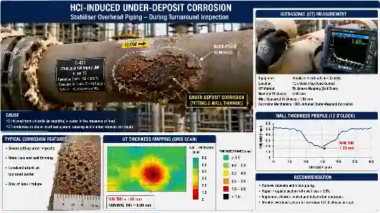
HCl Corrosion (Chlorided Alumina Catalyst Systems)
Cause: Organic chloride injection to maintain catalyst activity produces HCl in the reactor effluent. “Many refinery operators consider the isomerization unit one of the quietest units in the gasoline section — until feed contamination or chloride corrosion suddenly creates major operational headaches.”
If the stabiliser overhead water wash is inadequate or the pH control fails, HCl condenses in overhead piping and equipment. Location: Stabiliser overhead condenser, reflux drum, overhead vapour nozzles, and any low-point dead-legs. Inspection method: UT thickness scanning (grid mapping), visual inspection of internal surfaces, pH monitoring of overhead water wash. Relevant code: API 571 (Damage Mechanism 3 — HCl Corrosion), API 510.
Catalyst Deactivation and Poisoning
Cause: Water, sulphur compounds, nitrogen, and oxygenates in the feed permanently deactivate chlorided alumina catalysts. Zeolite catalysts are more tolerant but still affected by heavy metals and organic silicon compounds. Location: Reactor catalyst beds. Inspection method: Monitoring of reactor inlet/outlet temperature differential, octane analysis of product, and catalyst activity tests. What inspectors commonly find during catalyst changeout is uneven catalyst bed compaction and localised hot spots caused by channelling — both of which are missed by simple average temperature monitoring. Standard: Catalyst vendor technical specifications and refinery QA procedures.
Stress Corrosion Cracking (SCC) of Stainless Steel
Cause: Chloride-containing process streams in combination with elevated temperatures and tensile stresses cause chloride SCC in austenitic stainless steels (e.g., 304, 316 SS). Location: Stabiliser overhead system, any SS instrumentation tubing, sample coolers, and heat exchanger tubes in wet HCl service. Inspection method: Penetrant testing (PT) or eddy current testing (ECT) for surface-breaking cracks; ACFM or phased array UT for subsurface indications. Relevant code: API 571, ASME Section VIII Div.1 fitness for service under API 579-1/ASME FFS-1.
Fouling of Feed/Effluent Heat Exchanger
Cause: Polymer formation from diolefins or trace oxygenates in the feed deposits on exchanger tubes, reducing heat transfer efficiency and raising fired heater fuel consumption. Location: Feed/effluent shell-and-tube exchanger tube bundles. Inspection method: Performance monitoring (LMTD and U-value trending), hydrojetting, and internal visual inspection during turnaround. In practice, fouling of this exchanger is often the first operational indicator of an upstream feed quality problem, appearing as rising heater outlet temperature at constant feed rate weeks before other symptoms emerge.
Compressor Valve and Seal Failures
Cause: Reciprocating hydrogen recycle compressors operate continuously and are subject to valve wear, rod seal degradation, and HCl-induced corrosion on metallic components. Location: Suction and discharge valves, piston rod packing, cylinder bore. Inspection method: Vibration monitoring, performance curve trending, and scheduled valve/seal replacement per API 618 interval recommendations.
Isomerization Unit vs. Catalytic Reformer — What Is the Difference?
A common misconception is that isomerization and catalytic reforming are the same process because both use platinum catalysts and process naphtha. In reality, they are fundamentally different in feed, severity, purpose, and products. Reforming targets the C7–C10+ heavy naphtha fraction and operates at much higher severity to produce aromatic-rich reformate. Isomerization targets the lighter C5/C6 fraction and operates at low severity to produce a branched, non-aromatic product.
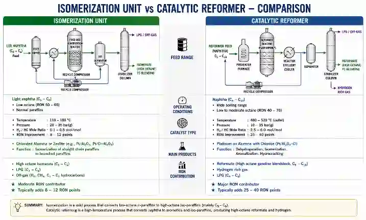
| Parameter | Isomerization Unit | Catalytic Reformer |
|---|---|---|
| Feed | Light naphtha C5–C6 (30–70°C) | Heavy naphtha C7–C10 (85–180°C) |
| Purpose | Rearrange paraffins for RON gain | Aromatise naphthenes and paraffins |
| Catalyst | Pt/chlorided alumina or Pt/zeolite | Pt-Re or Pt-Sn on gamma-alumina |
| Temperature | 110–280°C | 480–530°C |
| Pressure | 20–35 bar | 5–35 bar (semi-regen to CCR) |
| H2 production | Net consumer of H2 | Major H2 producer |
| Benzene in product | Effectively zero | High (3–7 vol%) |
| Product RON | 83–92 | 95–105 |
| Coke formation | Minimal | Significant (requires regeneration) |
| Inspection risk | HCl corrosion (chlorided units) | High-temperature oxidation, creep |
Conclusion
An isomerization unit is one of the most strategically important processing units in a modern refinery — it delivers reliable octane improvement from a low-severity, low-cost process that produces essentially zero benzene in the product. For anyone working in refinery inspection, process engineering, or operations, understanding the isomerization process — from feed drying through catalyst reaction to stabiliser overhead corrosion management — is a practical necessity, not just an academic exercise. With fuel quality regulations continuing to tighten globally, refineries that have invested in isomerization capacity with recycle configurations are significantly better positioned to meet both octane targets and aromatics limits simultaneously. Any inspector or engineer working on these units should be fully conversant with API 571 damage mechanisms, particularly HCl corrosion and chloride SCC, which are the dominant integrity threats on chlorided alumina catalyst systems.
Frequently Asked Questions
What is the use of isomerization in a refinery?
What is called isomerization in chemistry?
What types of catalysts are used in an isomerization unit?
What is the typical RON improvement from an isomerization unit?
How often does an isomerization unit require a turnaround?
Does an isomerization unit produce or consume hydrogen?
What standards govern inspection of an isomerization unit?
Suggested Posts
Why Is It Called a Delayed Coker? Process Explained
What Is an Amine Recovery Unit? Process, Working & ARU in Oil Refineries
About The Author
